Carson Shollenbarger, Jason Tafoya, Brian Schulz, Dan Schulz, John Pickron, Donald Sipes Jr. Optical Engines Inc., 2829 W. Colorado Avenue, Colorado Springs, CO, USA 80904-2443
ABSTRACT
In this work, we discuss a novel architecture for an all-fiber linearly polarized counter-pumped linear amplifier utilizing an 85 μm core diameter rod fiber. Signal light is launched directly into the core region of the rod fiber with high coupling efficiency via a monolithic mode-field adapter (MFA) splice. The free-space coupling optics and alignment for counter-pumping the amplifier are contained and fixed in a small, ruggedized packaging. Both the monolithic MFA splice and fixed free-space optics lock the signal and pump coupling efficiencies, allowing the device to be handled as if it were entirely monolithic. Over 18 dB of gain was achieved during power testing as a single-stage linear amplifier. Methodologies for advancing this architecture into a multistage linear amplifier to achieve higher peak and average powers are discussed. Simulations and models are used to define the signal power, pump power, gain fiber geometries, and gain stage lengths required to achieve 1 mJ pulse energies in 1 ns pulse durations, as well as predict the resulting B-integral, amplified spontaneous emission (ASE) levels, and unabsorbed pump power. The feasibility of realizing such an amplifier architecture is then discussed as a conclusion.
Keywords: Monolithic, linearly polarized, pulsed, high-energy, counter-pumped, rod fiber, fiber laser, PCF.
1. INTRODUCTION
Over the past decade, fiber lasers have continued to demonstrate improvements in achievable output power, beam quality, and non-linearity suppression [1]. As a result, fiber lasers have found themselves becoming increasingly popular amongst a continuously expanding array of applications. Such applications include, but are not limited to, plastic welding, industrial processing and machining, medical procedures and operations, academic pursuits and experiments, and demonstrations of phenomena in advanced physics [1-4]. As the interest in fiber lasers has continued to increase, the performance demands of such lasers have continued to increase in tandem. To meet these growing performance demands, optical fiber manufacturers have produced gain fibers capable of achieving higher average and peak powers, better single-mode operation at larger mode-field diameters, greater energy extraction, increased levels of mode filtering, and stronger suppression of performance-stunting nonlinearities [5-6, 12].
One such gain fiber of notable interest is the rod-type photonic crystal fiber (PCF). These large mode-area fibers offer high levels of available gain in short fiber lengths, making them ideal for pulsed laser applications. Improvements have been made to these fibers that now allow them to operate single-mode while withstanding high peak and average powers while preserving temporal and spectral purity. Megawatt peak powers, millijoule level pulse energies, and multi-hundred watt average powers have been achieved using PCF rods [6-7]. However, a caveat to these PCF rods, as well as most recently developed high-performance gain fibers, is an increased difficulty in handling and processing them. PCF rods have stringent environmental and processing requirements that must be met for them to perform optimally. Meeting these requirements has proven challenging enough for most end users to resort to free-space coupling as a means of seeding and pumping these PCF rods [5, 7-10].
The motivation for producing monolithic devices incorporating these PCF rods is in eliminating the free-space coupling aspect of the device’s design and operation. This would result in noticeable improvements in reliability and ease of operation. Additionally, some primary advantages of monolithic fiber lasers include their rigidity, stability, and compact designs [5]. Some of these advantages are diminished or lost entirely when free-space coupling is involved. However, as a pumping method, counter-pumping provides substantial performance benefits over co-pumping with regards to inversion population, thermal management, and nonlinearity mitigation [11-13, 15-16]. Hence, a means of identifying, eliminating,
and replacing unnecessary free-space couplings with monolithic fiber splices while identifying and monolithically locking pertinent free-space couplings would become paramount for optimal device performance.
In this paper, we discuss a novel architecture for an all-fiber linearly polarized counter-pumped linear amplifier utilizing an 85 μm core diameter PCF rod. Signal light is launched directly into the core region of the rod fiber with high coupling efficiency via a monolithic mode-field adapter (MFA) splice. The free-space coupling optics and alignment for counter-pumping the amplifier are contained and fixed in a small, ruggedized package. This accomplishes the goals outlined above for meeting optimal device performance, tailoring the ideal applications of the amplifier towards those found among high-energy pulsed fiber lasers. The device is then mounted in a housing package and power tested, where over 18 dB of gain was achieved when tested as a single-stage linear amplifier. Methodologies for advancing this architecture into a multistage linear oscillator to achieve higher peak and average powers are discussed. Simulations and models are used to define the necessary signal powers, pump powers, gain fiber geometries, and gain stage lengths required to achieve 1 mJ pulse energies in 1 ns pulse durations, as well as predict the resulting B-integral, amplified spontaneous emission (ASE) levels, and unabsorbed pump powers. The results of the amplifier build, power testing, and the feasibility of realizing a composite amplifier architecture are then discussed in conclusion.
2. AMPLIFIER ARCHITECTURE
Commercially available single-mode polarization-maintaining (PM) germanium-doped double-clad fiber (GDF) is used as the signal input fiber. Specifically, PM 10/125 is chosen, as it is commonly used as the output fiber in a wide range of commercially available seed sources. This enables the amplifier operator to use readily available fiber processing equipment to splice the amplifier directly into their seed source of choice. The length of PM 10/125 fiber is kept intentionally long during the fabrication process as this allows all fiber processing techniques ample fiber length to work with. Additionally, for pulsed applications, should a fiber-based pre-amplifier be used between the seed source and the main PCF rod amplifier, the PM 10/125 fiber can be cut back as necessary for nonlinearity mitigation.
The output of the GDF PM 10/125 signal fiber is coupled into a short length of commercially available GDF PM 25/250 through a monolithic MFA splice. PM 25/250 is used as an intermediary fiber because the mode-field diameter (MFD) adaptation between PM 25/250 and 85 μm diameter rod fiber is more efficient and easily fabricated compared to that of a MFD adaptation between PM 10/125 and 85 μm rod fiber. Additionally, the MFA between PM 10/125 and PM 25/250 is accomplished using a short adiabatic thermal taper. After the MFA, a cladding light stripping (CLS) region is embedded into the PM 25/250 fiber to remove and prevent any backward-propagating unabsorbed pump and cladding light from entering the thermal taper found in the MFA. This mitigates such light from being absorbed in the PM 10/125 acrylate buffer after the resulting numerical aperture (NA) increase that would occur from propagating backwards through the thermal taper.
Signal light from the GDF PM 25/250 is adapted and launched into an 85 μm diameter ytterbium-doped PCF rod with high coupling efficiency via a monolithic MFA splice. This MFA measures approximately 1.5 mm in length and adapts both forward-propagating signal light and backward-propagating pump light between the PM 25/250 and 85 μm PCF rod fibers. The MFA is optimized for highest coupling efficiency over shortest necessary adaptation length. For pulsed applications, the short MFA length is ideal for mitigating the accumulation of nonlinearities, particularly self-phase modulation (SPM). Furthermore, should the passive PM 25/250 fiber be substituted with active PM 25/250 fiber, adding another gain stage between the seed source and PCF rod, which this architecture supports, the importance of the short MFA is further emphasized as it minimizes fiber length between gain stages, mitigating the accumulation of SPM.
To meet the strict processing requirements needed to efficiently couple into the PCF rod, the fiber is cleaved on both sides to angles less than 0.2 degrees. These cleaves were achieved using commercially available fiber processing and cleaving equipment. White light was injected into the fiber to illuminate the microstructure embedded into the rod’s geometry. The microstructure, consisting of many small, closely spaced air holes, is paramount to the guiding properties and performance of the fiber. Therefore, ensuring the microstructure is not damaged, collapsed, or contaminated during processing and handling is equally important. Figure 1 depicts several flat 85 μm core diameter PCF rod cleaves with white light used to illuminate the intact microstructures.

Figure 1. Several flat 85 μm core diameter PCF rod cleaves with white light injection for microstructure illumination.
The PM 25/250 MFA is aligned, coupled, and spliced to the PCF rod using a commercially available fiber splicing machine. Prior to coupling and splicing, the PM 25/250 MFA output is thoroughly characterized. Cleave angles, core light measurements, cladding light measurements, polarization extinction ratio (PER), MFD, and beam quality are all assessed. Once loaded into the fiber splicing machine, vertical, horizontal, and angular fiber offsets can be measured and minimized. Equation 1 below uses Marcuse’s equation to calculate the expected splice loss between two single mode fibers:

where 𝜔1 and 𝜔2 are the mode-field radii of fiber 1 and fiber 2, respectively, 𝛿 is the lateral offset between fiber cores, 𝜃 is the angular offset between fiber cores, and 𝑛 is the refractive index of the fiber cores. RP Fiber Power, a simulation software suite, is used to predict the amount of absorption 1064 nm signal light is expected to experience through the length of ytterbium-doped PCF rod. These two calculations result in a metric goal: the theoretical maximum measurable output power. Coupling optimization is performed in the fiber splicing machine using nanometer-resolution 5-axis stage controls to minimize the lateral and angular offsets between fibers. This optimization minimizes the difference between measured signal light contained in the core region of the PCF rod to the metric goal mentioned previously. Additionally, the beam is imaged to ensure the fundamental mode is guided and dominates all other potentially present higher-order modes (HOM’s). Figure 2 shows an image of the beam observed out of the PCF rod at the completion of coupling optimization. An orthographic projection is applied to depict the true gaussian nature of the guided mode. The RMS between the measured beam profile’s gaussian-shape and a true gaussian profile was calculated to be 0.983.
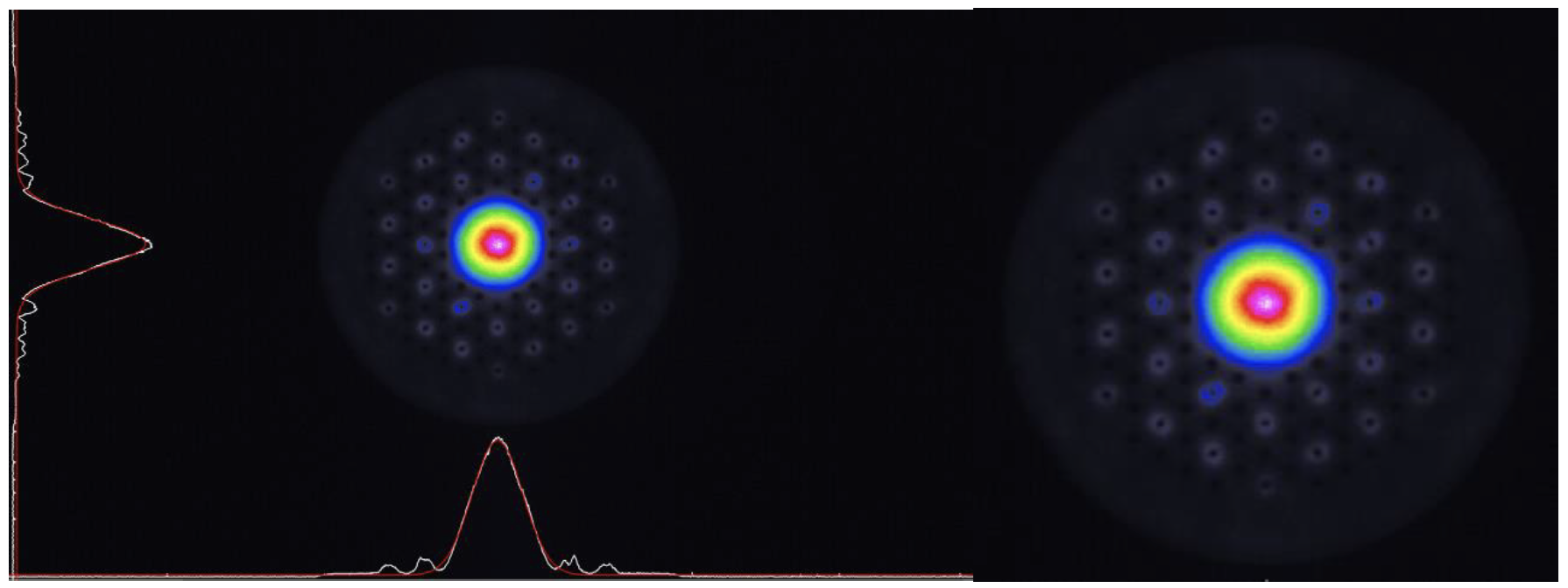
Figure 2. Beam image observed out of the 85 μm core diameter PCF rod at the conclusion of coupling optimization.
After the conclusion of coupling optimization, the PM 25/250 MFA is spliced monolithically to the 85 μm core diameter PCF rod. The splice is then rigidly isolated and packaged. The packaging locks the coupling efficiency and protects the splice from potential structural damage and contamination. Figure 3 depicts the PM 25/250 MFA spliced to the PCF rod. Once the splice is packaged, core light measurements, cladding light measurements, PER, and beam quality are recorded and assessed against the PM 25/250 MFA output measurements. Signal light coupling efficiency was measured to be 95.6%. Note that the PCF rod does not have PM stress rods like conventional PM optical fiber. However, due to the PCF rod being a true rod fiber by design, a given launched polarization state will be maintained through the rod should the fiber be held straight. A PER of 15.1 dB was measured when both PM 25/250 and PCF rod were held straight.
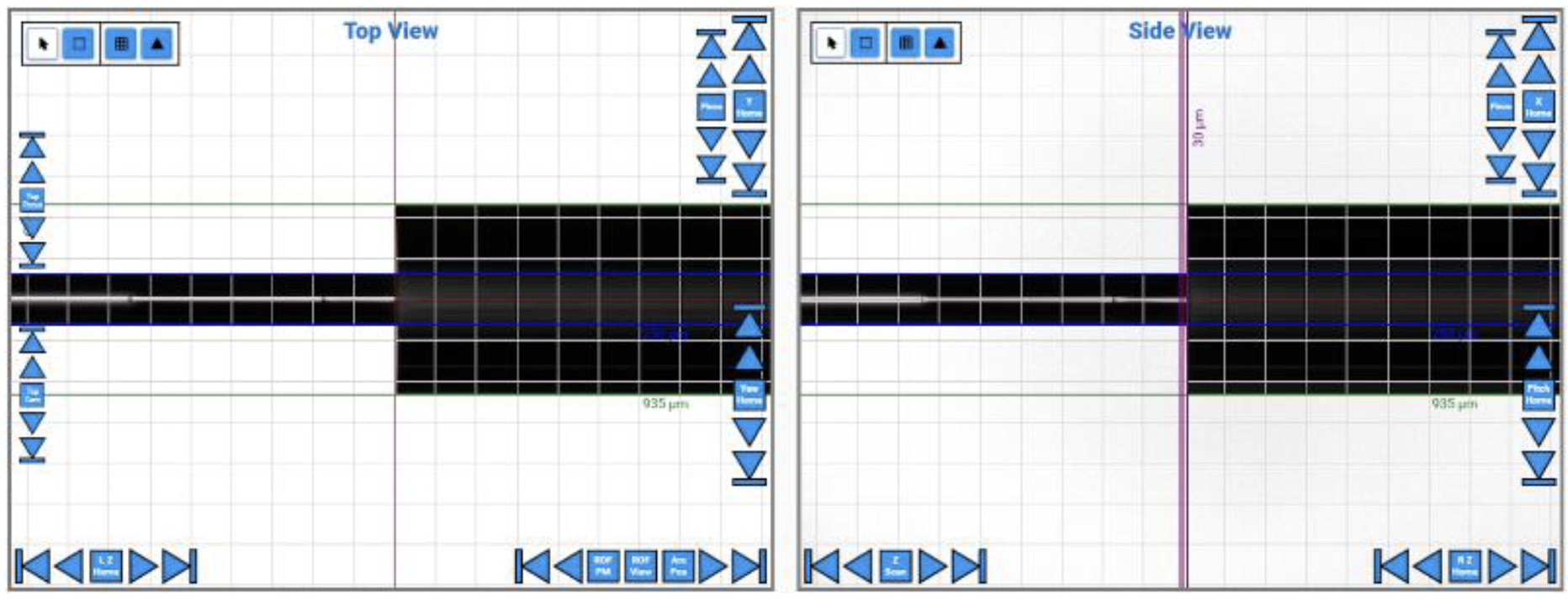
Figure 3. PM 25/250 MFA spliced to the 85 μm core diameter PCF rod using a commercially available fiber splicing machine.
The end caps and coupling optics for counter-pumping the amplifier are housed and contained in an architecture defined as the Counter-Pumped Tapered End Cap (CPTEC) assembly. A simple schematic illustrating the principles of the CPTEC architecture can be found in figure 4. This patented architecture utilizes AR-coated tapers as non-imaging optics, an AR-coated retroreflector, and a precision made sapphire housing block to align and couple pump light launched from commercially available GDF multimode (MM) 220/242 fiber through the retroreflector and into the cladding of the PCF rod. AR-coated end caps are spliced to the output of the PCF rod and 220/242 fibers. The end capped fibers are inserted into a precision made sapphire block parallel to each other. An AR-coated retroreflector in the form of a right angle mirror assembly reflects and directs the pump light launched from the MM 220/242 fiber into the cladding of the PCF rod fiber through the other tapered end cap. This assembly is optimized actively for pump coupling efficiency using an 808 nm source. Once coupling optimization is completed, the fibers, tapered end caps, and retroreflectors are rigidly fixed to the sapphire housing block. This locks the pump coupling efficiency and allows the structure to be handled as if it were entirely monolithic [17]..

Figure 4. Simple schematic of the CPTEC architecture. Signal and pump light are visualized by green and red arrows, respectively.
Once the CPTEC structure is complete, the amplifier is loaded into a water-cooled anodized aluminum housing. The amplifier is fixed into the housing such that potential stress on the PCF rod is minimized while contact with the cooling surfaces is maximized. If the PCF rod fiber is fixed to the housing too rigidly, then thermal expansion of the aluminum housing during operation or changes in environment would exert stress and strain on the PCF rod, negatively impacting the performance of the amplifier. Additionally, such stresses risk breaking any of the splices found throughout the amplifier. Figure 5 shows a schematic of the completed amplifier architecture. After the amplifier is fixed in the aluminum housing, the device is power tested as a single stage linear amplifier.

Figure 5. Schematic of monolithic counter-pumped 85 μm core diameter PCF rod amplifier.
3. EXPERIMENTAL TESTING AND RESULTS
A tunable continuous wave (CW) ring laser was set to 1030 nm and used as a seed source. The PM 10/125 fiber-coupled output is spliced to the PM 10/125 amplifier signal input fiber. A 50 W 976 nm VBG locked fiber-coupled direct diode pump source is spliced to the MM 220/242 amplifier pump input fiber. A power meter is stationed in front of the aluminum housing output window to capture the amplified signal. A drawing of the setup used to power test the PCF rod amplifier can be found in figure 6.
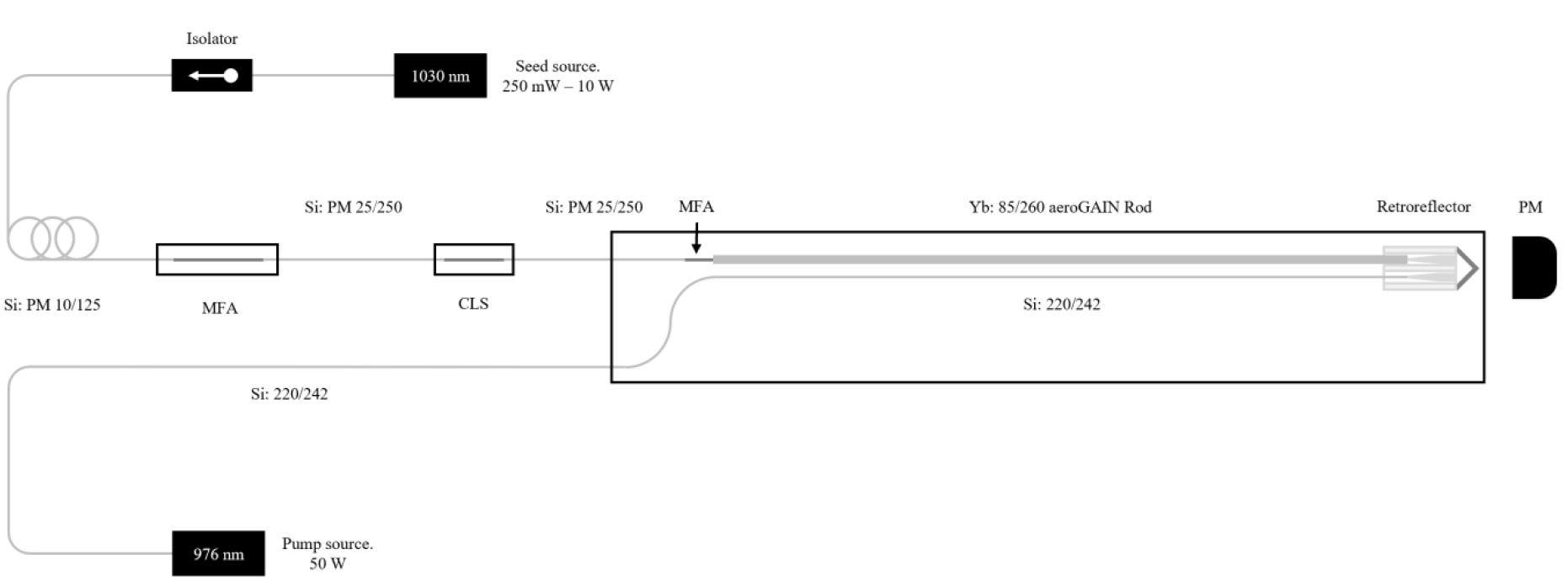
Figure 6. Schematic of setup used for power testing the PCF rod amplifier.
The first power testing experiment had the tunable source set to 250 mW output power centered at 1030 nm. 50 W of 976 nm pump light was launched through the amplifier. The second power testing experiment had the tunable source set to 10 W output power centered at 1030 nm. Again, 50 W of 976 nm pump light was launched through the amplifier. Forward power, backward power, thermal, beam image, and system efficiency measurements were recorded for both experiments. The purpose of the first experiment was to test small signal gain. This would ascertain the available gain the PCF rod fiber offers as a solitary gain stage. The purpose of the second experiment was to shift the gain dynamics of the amplifier and analyze the resulting thermal behavior exhibited by the PCF rod. By seeding the amplifier harder, the unabsorbed pump near the end of the PCF rod decreases, while the gain at the front of the PCF rod increases. Additionally, this would force the amplifier to run at higher average power. The output beam was imaged at maximum average power where no distortions in beam shape or quality due to transverse modal instability (TMI) were observed. Understanding the changes in amplifier performance was another goal of the second power testing experiment.
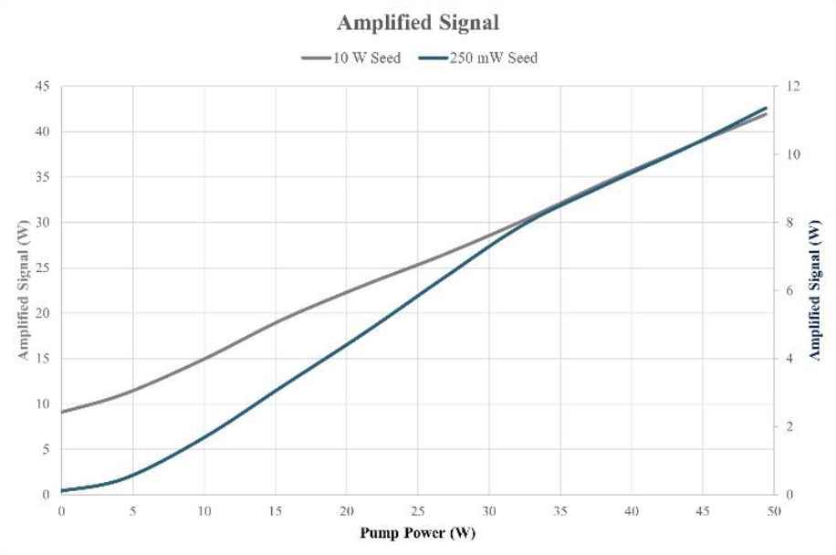
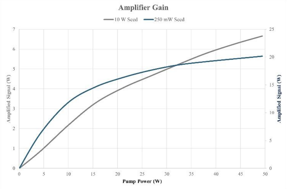
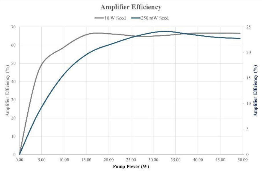
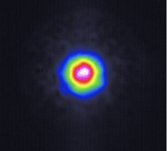
Figure 7. Results of power testing. Beam image at 50 W incident 976 nm pump power when seeded with 10 W at 1030 nm.
The results from power testing are shown in figure 7. For experiment one, 11.35 W of amplified 1030 nm signal light was measured out of the amplifier when 250 mW of 1030 nm seed and 50 W of 976 nm pump light was injected. This results in an amplifier efficiency of 22.75% and an amplifier gain of 20.14 dB. Due to the small signal power, the low efficiency and high gain is understandable. The backward propagating power, when expressed as a percentage of the forward propagating power, was measured at 0.002%. For experiment two, 41.9 W of amplified 1030 nm signal light was measured out of the amplifier when 10 W of 1030 nm seed and 50 W of 976 nm pump light was injected. This results in an amplifier efficiency of 66.5% and an amplifier gain of 6.66 dB. In this case, due to the high signal power, the high efficiency and low gain is understandable. The backward propagating power, when expressed as a percentage of the forward propagating power, was measured at 0.003%. With regards to differences in thermal behavior between experiments, at high seed powers, the temperature at the end of the PCF rod, near the PM 25/250 MFA, was 1.73 times lower than when ran at low seed powers. Conversely, at high seed powers, the temperature at the front of the PCF rod, near the CPTEC assembly, was 2.22 times higher than when ran at low seed powers.
4. FUTURE WORK
For this endeavor, the architecture was intentionally designed as a single stage linear amplifier. Evaluating the potential available gain of the PCF rod itself as a single stage of amplification was the primary objective of the project. However, it would not be difficult to add additional gain stages to this amplifier architecture. For example, as stated previously, the length of GDF PM 25/250 could easily be replaced with ytterbium-doped double-clad fiber (YDF) PM 25/250. The CLS embedded in the GDF PM 25/250 fiber would interfere if replaced with YDF PM 25/250, but this component could easily be moved and implemented into the MFA architecture between GDF PM 10/125 and the YDF PM 25/250. Adding a short length of YDF PM 25/250 would provide the PCF rod with stronger seed power, as well as increase the total available system gain. Additionally, a pre-amplifier utilizing YDF PM 10/125 could also be used. This would allow the now two stage composite PCF rod amplifier to be seeded strongly enough to ensure safe thermal operation. Figure 8 below depicts a schematic for such an amplifier. It is important to note that, for pulsed applications particularly, fiber lengths between gain stages should be minimized to prevent the onset and accumulation of SPM. SPM is quantified by measuring the B-Integral defined as:

where 𝜆 is the vacuum wavelength, 𝑛2 is the nonlinear refractive index, 𝜔 is mode-field radius, and 𝑃(𝑧) is power over amplifier length [16]. B-Integral is measured in radians and represents the nonlinear phase shift induced by SPM.
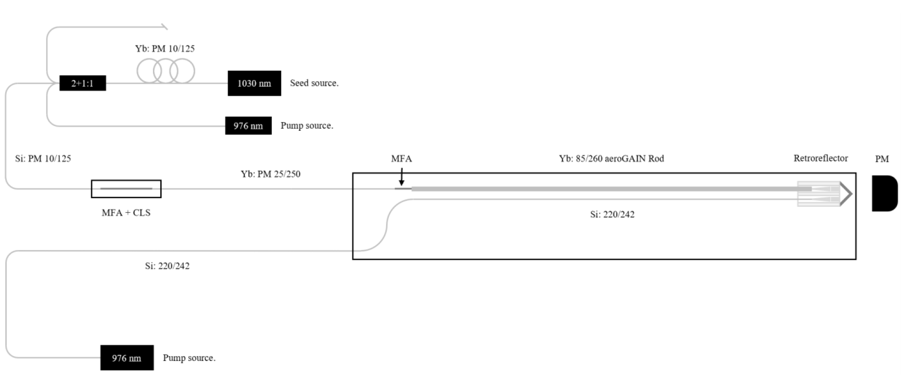
Figure 8. Schematic for a composite two stage PCF rod amplifier with additional pre-amplifier.
Such an amplifier is modeled using RP Fiber Power. The simulation software suite is designed for modeling complex multi-stage fiber amplifiers and waveguides. Simulations allow a wide range of variable manipulations, resulting in a flexible and believable modeling tool for accurately predicting the behavior of complex fiber laser architectures. The goal of the model is to produce 1 mJ level pulse energies in 1 ns pulse lengths at 1030 nm center wavelength. Pre-amplifier output parameters, gain stage fibers, gain stage lengths, and necessary main amp pump power will all be optimized for achieving 1 mJ pulse energies at 1 ns pulse lengths with minimal B-Integral. Amplified spontaneous emission (ASE) levels will also be modeled, as well as any evolutions in spectra.
Using commercially available ns pulsed fiber-coupled seed sources operating at 1030 nm, an approximately 100 mm length of YDF PM 10/125 fiber can be counter-pumped with 9 W of 976 nm pump light to achieve 50 uJ pulse energies in 1 ns pulse durations at 100 kHz. The seed wavelength is 1030 nm with a bandwidth of 2 nm FWHM. These are reasonable and safe operating parameters for a YDF PM 10/125 based pre-amplifier. These pulses are then coupled into the main two stage composite PCF rod amplifier.
A 300 mm length of commercially available YDF PM 25/250 is used for the first stage of amplification. Using an identical PM 25/250 MFA discussed in section 3, the forward propagating signal light is adapted into the 804 mm long 85 μm core diameter PCF rod used as stage two, while the backward propagating unabsorbed pump light from stage two is adapted into stage one. This architecture uses the unabsorbed pump from stage two to pump stage one. This efficiently utilizes pump light without having to incorporate additional pump combiners and pump sources between gain stages. Any backward propagating unabsorbed pump from stage one is then removed in the CLS embedded in the MFA (see figure 8). 130 W of narrow bandwidth 976 nm VBG locked pump light is coupled into stage two. 22 W of unabsorbed pump from stage two is then coupled into stage one. 16.1 W of unabsorbed pump is then removed in the CLS. With the defined seed output parameters, gain stage fibers, gain stage lengths, and pump powers, the simulation predicts 1.01 mJ pulse energies with 0.950 MW peak powers in 1 ns pulse lengths. 101 μW of forward ASE and 42.7 μW of backward ASE are predicted as well. Additionally, a total B-Integral value of 53 radians was calculated. The results from the modeling can be seen below in figure 9.
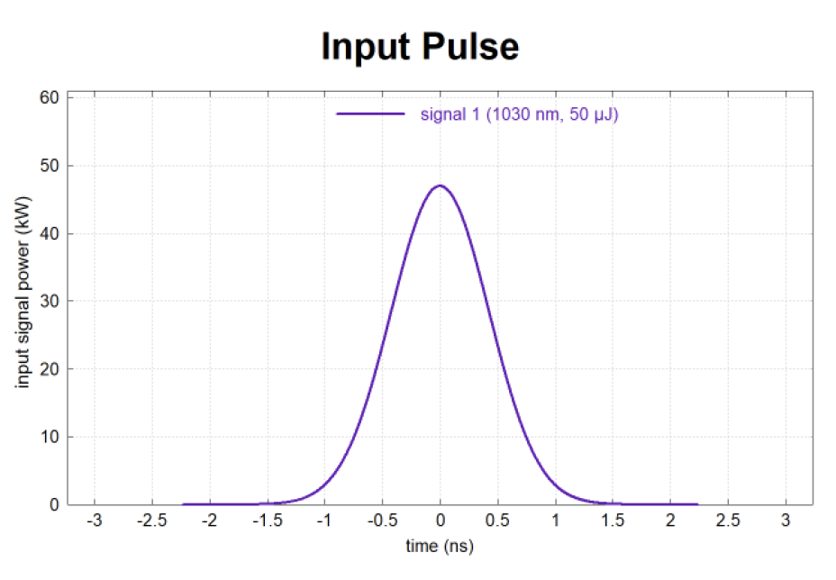
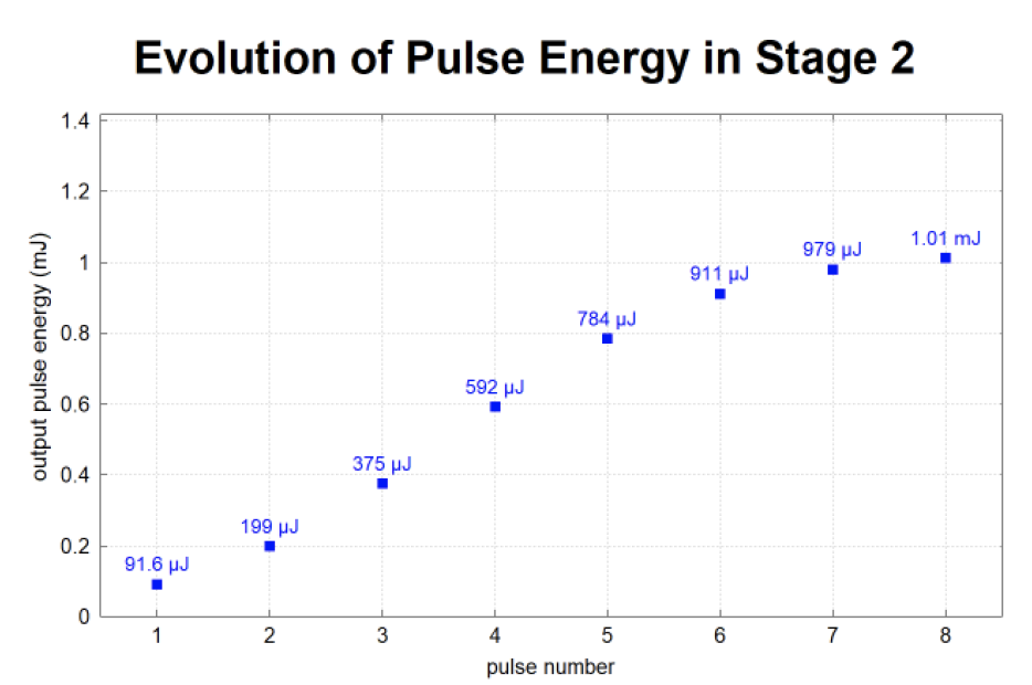
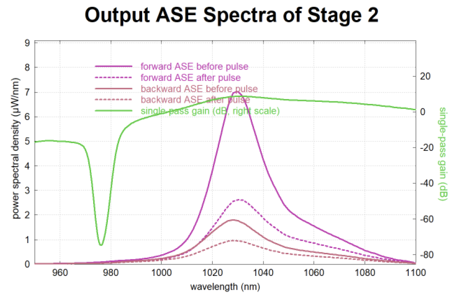
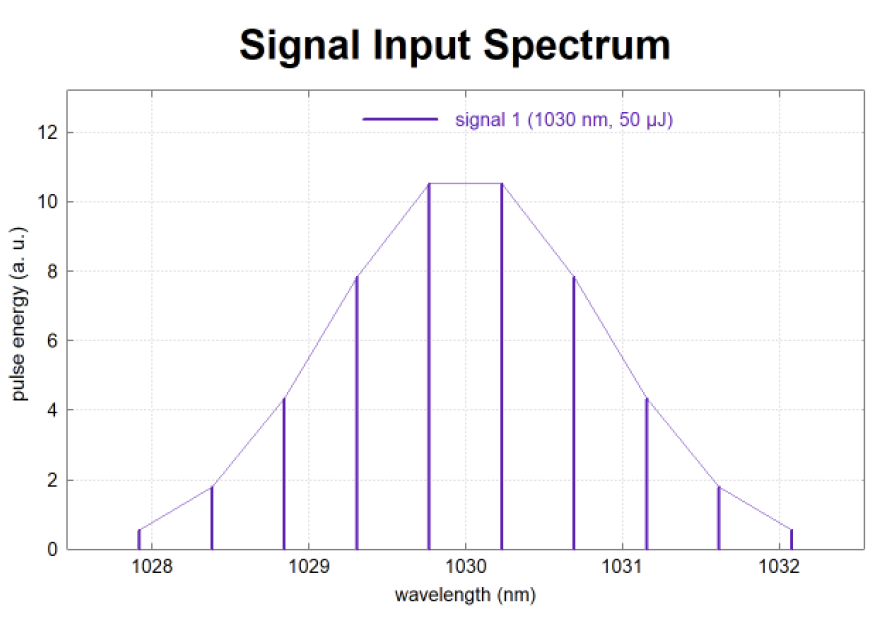
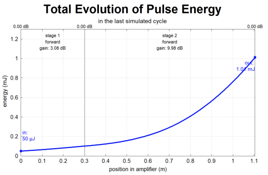
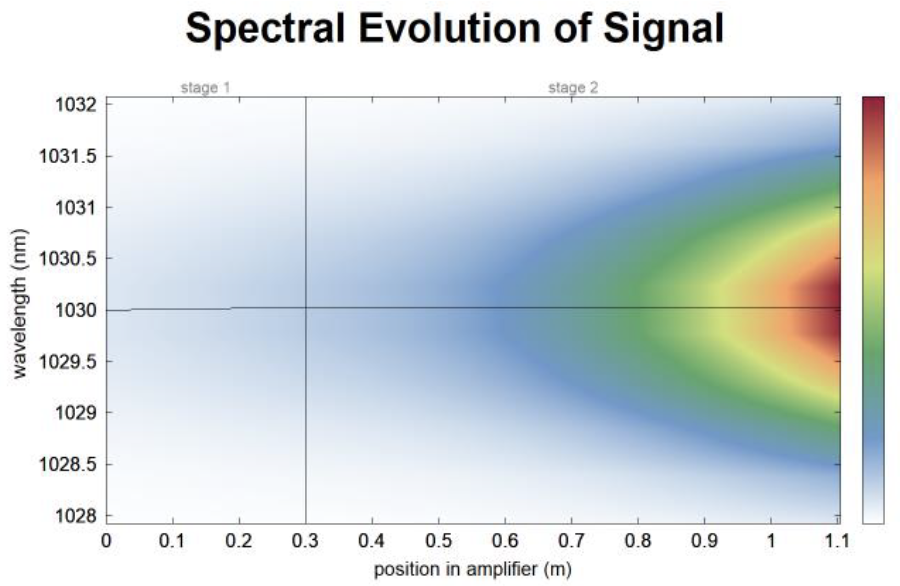
Figure 9. Results from RP Fiber Power modeling of a composite two stage PCF rod amplifier with additional pre-amplifier.
5. CONCLUSION
In conclusion, a monolithic linearly polarized counter-pumped single stage linear amplifier utilizing an 85 μm core diameter photonic crystal fiber rod was designed, fabricated, and tested successfully. Power testing results promote the validity of the design. Achieving over 95% signal coupling efficiency and 18 dB of gain in an 804 mm long amplification stage is an exciting prospect for high-energy pulsed laser applications. Furthermore, when seeded strongly, optical efficiencies greater than 66% were achieved, and the thermal performance implied reliable long-term operation. Literature suggests that commercially available PCF rod fibers can withstand the pulse energies, peak powers, and average powers the simulated composite two stage PCF rod amplifier would require [5,7]. Combined with the signal coupling efficiencies, PER, and beam quality results gathered during power testing, the realization of such an amplifier architecture appears feasible. Producing a 976 nm narrow bandwidth VBG locked fiber-coupled direct diode pump source is trivial. A ns pulsed fiber-coupled 1030 nm source for adequately seeding the amplifier is to be either produced or procured. Following the procurement of the pump and seed sources, future endeavors exist to fabricate this two stage composite amplifier architecture.
REFERENCES
[1] D. Richardson, J. Nilsson, and W. Clarkson, “High power fiber lasers: current status and future perspectives [Invited],” J. Opt. Soc. Am. B 27, B63-B92 (2010).
[2] Heinrich Endert, Almantas Galvanauskes, Gregg Douglas Sucha, and Rajesh S. Patel “Novel ultrashort-pulse fiber lasers and their applications”, Proc. SPIE 4426, Second International Symposium on Laser Precision Microfabrication, (25 February 2002); https://doi.org/10.1117/12.456810.
[3] Mark C. Pierce, Stuart D. Jackson, Paul S. Golding, Ben Dickinson, Mark Russell Dickinson, Terence A. King, and Philip Sloan “Development and application of fiber lasers for medical applications”, Proc. SPIE 4253, Optical Fibers and Sensors for Medical Applications, (4 June 2001); https://doi.org/10.1117/12.427916.
[4] T. Westphaling, “Pulsed fiber lasers from ns to ms range and their applications,” Physics Procedia 5, 125-136 (2010).
[5] M. Pedersen, M. Johansen, A. Olesen, M. Michieletto, M. Gaponenko, and M. Maack, “175 W average power from a single-core rod fiber-based chirped-pulse-amplification system,” Opt. Lett. 47, 5172-5175 (2022).
[6] X. Ma, C. Zhu, I. Hu, A. Kaplan, and A. Galvanauskas, “Single-mode chirally-coupled-core fibers with larger than 50μm diameter cores,” Opt. Express 22, 9206-9219 (2014).
[7] F. Di Teodoro and C. Brooks, “Multi-MW peak power single-transverse mode operation of a 100 micron core diameter, Yb-doped photonic crystal rod amplifier,” Proc. SPIE 6453, Fiber Lasers IV: Technology Systems, and Applications, 645318 (22 February 2007).
[8] J. Limpert, N. Deguil-Robin, I. Manek-Hönninger, F. Salin, F. Röser, A. Liem, T. Schreiber, S. Nolte, H. Zellmer, A. Tünnermann, J. Broeng, A. Petersson, and C. Jakobsen, “High-power rod-type photonic crystal fiber laser,” Opt. Express 13, 1055-1058 (2005).
[9] M. Ghawas, V. Freysz, L. Müller, S. Cassagnère, and E. Freysz, “High power ytterbium rod-type fiber laser delivering tunable picosecond pulses,” Opt. Express 30, 44569-44579 (2022).
[10] Lv, Zhiguo & Yang, Zhi & Li, Qianglong & Li, Feng & Wang, Yishan & Zhao, Wei & Yang, Xiaojun. (2020). “Photonic crystal rod-based high-performance ultrafast fiber laser system,” High Power Laser Science and Engineering. 8. 10.1017.
[11] Roohforouz, Ali & Chenar, Reza & Rezaei-Nasirabad, Reza & Azizi, Saeed & Hejaz, Kamran & Golshan, Ali & Abedinajafi, Ali & Vatani, Vahid & Seyed, & Nabavi, Hassan. (2021). “The effect of population inversion saturation on the transverse mode instability threshold in high power fiber laser oscillators”, Scientific Reports. 11. 1-7.
[12] C. Wang, H. Xiao, X. Xi, W. Liu, R. Li, Z. Pan, H. Yang, Z. Yan, Z. Chen, L. Huang, M. Wang, B. Yang, X. Wang, P. Ma, and Z. Wang, “10 kW tandem pumping fiber amplifier with good beam quality based on tapered ytterbium-doped fiber,” Opt. Express 31, 40980-40990 (2023).
[13] W. Dan, Q. Han, Q. Jia, K. Ren, and T. Liu, “Numerical comparison of pumping methods for high-power Er/Yb-codoped fiber lasers,” Appl. Opt. 60, 2560-2566 (2021).
[14] J. Limpert, F. Roser, T. Schreiber and A. Tunnermann, “High-power ultrafast fiber laser systems,” in IEEE Journal of Selected Topics in Quantum Electronics, vol. 12, no. 2, pp. 233-244, March-April 2006.
[15] G. P. Agrawal, “Nonlinear Fiber Optics”, 3rd Ed. (Academic, San Diego, Calif., 2001).
[16] M. Perry, T. Ditmire, and B. Stuart, “Self-phase modulation in chirped-pulse amplification,” Opt. Lett. 19, 2149-2151 (1994).
[17] Don L Sipes Jr., “Counter pumping a large mode area fiber laser”, U.S. Patent US-11342723-B2, May 24, 2022.
